| Back to Contents Page | Glossary |
 |
||||||||||||||||||||||||||||||||||||||||||
|
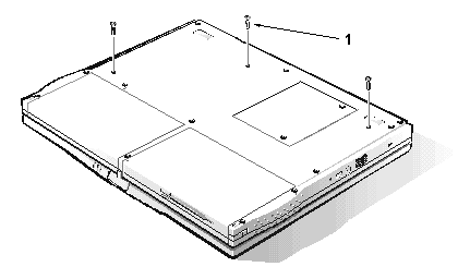
| Type of Screw | Torque |
| FPH 2.5 x 16 (3) | 3.5–4.0 kgf-cm |
| NOTE: You can remove the keyboard while the display assembly is still attached. However, Dell strongly recommends removing the display assembly before removing the keyboard to prevent cosmetic damage. |
 |
|
You can remove the keyboard without removing the palmrest. To remove the keyboard, see the exploded view of the palmrest assembly and perform the following steps:
| NOTE: The ZIF connector cap for the keyboard is stocked as a separate part. If the plastic connector cap is broken, you can snap a new one in place without having to replace the entire system board. |
| Type of Screw | Torque |
| FPH 2.5 x 5 (1) | 3.0–3.5 kgf-cm |
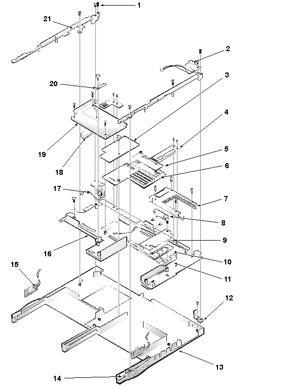
You can remove the infrared (IR) board without removing the palmrest. To remove the infrared board, see the exploded view of the base assembly and perform the following steps:
| NOTE: Reconnect the IR board to the system board by carefully threading the wires and connector by the I/O bracket and using a screwdriver to press on the connector to reseat it. |
You can remove the LVDS board without removing the palmrest. To remove the LVDS board, see the exploded view of the base assembly and perform the following steps:
| NOTE: For grounding purposes, an EMI tape may run from the LVDS board to the I/O bracket. Note the placement of the tape and, during installation, replace it in the same position. |
When installing the LVDS board, put pressure only on the areas where the connectors on the LVDS board and on the video board fit together. Pressing on other areas may flex the board and break connections.
| NOTE: The LVDS board is unique for each type of LCD panel. During installation, make sure that the LVDS board is the correct one for the panel and that any EMI tape attached to the board is replaced in its original position. |
| Type of Screw | Torque |
| FPH 2 x 3.5 (1) | 1.5–1.8 kgf-cm |
You can remove the heat-sink fin cover without removing the palmrest. To remove the heat-sink fin cover, see the exploded view of the base assembly and perform the following steps:
| Type of Screw | Torque |
| PNH 2 x 14 (2) | 1.5–1.8 kgf-cm |
You can remove the processor module assembly without removing the palmrest. To remove the processor module assembly, see the exploded view of the base assembly and perform the following steps:
When you install the processor module assembly, put pressure only on the areas where the connectors on the processor module assembly and on the system board fit together. Pressing on other areas may break pins or connections.
| Type of Screw | Torque |
| FPH 2.5 x 5 (1) | 3.0–3.5 kgf-cm |
You can remove the fan cover and fan without removing the palmrest. To remove the fan cover and fan, see the exploded view of the base assembly and perform the following steps:
| NOTE: Note the positioning of the fan and the routing of the fan cable carefully so that you can duplicate it during installation. An arrow on the top of the fan indicates that the flow of air is from the outside of the computer in to the board. |
| Type of Screw | Torque |
| FPH 2.5 x 14 (1) | 3.0–3.5 kgf-cm |
The modem card is an option available only to customers in the U.S. and Canada.
You can remove the modem card without removing the palmrest. To remove the modem card, see the exploded view of the base assembly and perform the following steps:
When you install the modem card, slip it into place under the system-board retaining clip. Put pressure only on the areas where the connectors on the modem card and on the video board fit together. Pressing on other areas may flex the card and break connections.
| Type of Screw | Torque |
| jack 2.5 x 4 (2) | 3.0–3.5 kgf-cm |
| FPH 2.5 x 14 (1) | 3.0–3.5 kgf-cm |
You can remove the video board without removing the palmrest. To remove the video board, see the exploded view of the base assembly and perform the following steps:
When you install the board, put pressure only on the areas where the connectors on the video board and on the system board fit together. Pressing on other areas may flex the board and break connections.
| Type of Screw | Torque |
| FPH 2.5 x 5 (2) | 3.0–3.5 kgf-cm |
| FPH 2.5 x 16 (1) | 3.0–3.5 kgf-cm |
To remove the system board rails, see the exploded view of the base assembly and perform the following steps:
When you install the rails, be sure that the speaker cables are not pinched.
| Type of Screw | Torque |
| FPH 2.5 x 14 (1) | 3.0–3.5 kgf-cm |
To remove the DC/DC board, see the exploded view of the base assembly and perform the following steps:
When you install the board, put pressure only on the areas where the connectors on the DC/DC board and on the system board fit together. Pressing on other areas may flex the board and break connections.
To remove the speakers, see the exploded view of the base assembly and perform the following steps:
| NOTE: The left and right speakers are interchangeable. Note the routing of the speaker cables through the plastic routing ribs for installation. |
| Type of Screw | Torque |
| PNH 2 x 14 (4) | 1.5–1.8 kgf-cm |
The PC Card cage is supplied as a part of the system board assembly. However, if only the PC Card cage needs replacement, use this procedure to remove and replace the PC Card cage. You do not need to remove the entire system board.
To remove the PC Card cage, see the exploded view of the base assembly and perform the following steps:
When you install the PC Card cage, ensure that the modem cable is routed correctly and is not pinched by the cage.
| Type of Screw | Torque |
| FPH 2.5 x 5 (1) | 3.0–3.5 kgf-cm |
| FPH 2.5 x 14 (1) | 3.0–3.5 kgf-cm |
To remove the system board, see the exploded view of the base assembly and perform the following steps:
To remove the audio jack board, see the exploded view of the base assembly and perform the following steps:
When you install the audio jack board, it is helpful to move the PC Card latches out of the way. Put pressure only on the areas where the connectors on the audio jack board and on the system board fit together. Pressing on other areas may bend the board and break connections.
| Back to Contents Page | Glossary |