Back to Contents Page Glossary

Base Assembly: Dell™ Inspiron™ 3500 Portable Computer

bullet.GIF (1107 bytes) Exploded View of Base Assembly bullet.GIF (1107 bytes) Video Board Removal
bullet.GIF (1107 bytes) Keyboard Removal bullet.GIF (1107 bytes) System Board Rails Removal
bullet.GIF (1107 bytes) Infrared Board Removal bullet.GIF (1107 bytes) DC/DC Board Removal
bullet.GIF (1107 bytes) LVDS Board Removal bullet.GIF (1107 bytes) Speaker Removal
bullet.GIF (1107 bytes) Heat-Sink Fin Cover Removal bullet.GIF (1107 bytes) PC Card Cage Removal
bullet.GIF (1107 bytes) Processor Module Assembly Removal bullet.GIF (1107 bytes) System Board Removal
bullet.GIF (1107 bytes) Fan Cover and Fan Removal bullet.GIF (1107 bytes) Audio-Jack Board Removal
bullet.GIF (1107 bytes) Modem Card Removal

Exploded View of Base Assembly

Exploded View of the Base Assembly
 
1 Ground springs (2)
2 Infrared board with 5-mm screw
3 Optional internal modem with 14-mm screw
4 EMI fin (2)
5 LVDS board
6 Video board with 4-mm jack screws (2) and 14-mm screw
7 PC Card cage with 14-mm screws (4)
8 Monitor connector cover
9 DC/DC board with 14-mm screw
10 Audio jack board
11 Audio jack shield
12 System-board retaining clip with 5-mm screw
13 Bottom plastic
14 Release latches
15 Speakers
16 system board (in EMI pan)
17 Fan and fan cover with 5-mm screw
18 Heat-sink fin
19 Processor module assembly with 14-mm screws (2)
20 System-board retaining clip with 14-mm screw
21 System board rails (2) with 5-mm screws (2) and 16-mm screw


Keyboard Removal

Type of Screw Torque
FPH 2.5 x 16 (3) 3.5–4.0 kgf-cm
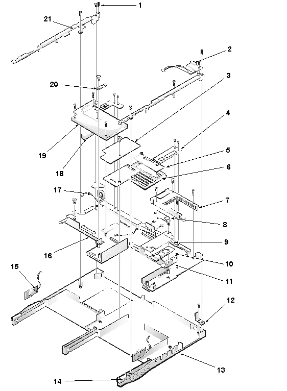
NOTE: You can remove the keyboard while the display assembly is still attached. However, Dell strongly recommends removing the display assembly before removing the keyboard to prevent cosmetic damage.
Keyboard Removal
1 16-mm screws (3)


You can remove the keyboard without removing the palmrest. To remove the keyboard, see the exploded view of the palmrest assembly and perform the following steps:

  1. Remove the display assembly.
  2. Place the computer base face down.
  3. Remove the three 16-mm keyboard screws from the bottom of the computer.
    The keyboard screws have a K tooled into the plastic beside them.
  4. Turn the computer face up.
  5. Lift the top edge of the keyboard up, and then slide the keyboard out from beneath the palmrest assembly.
    Do not try to completely remove the keyboard, because it is still attached to the system board by a cable.
  6. Disconnect the keyboard cable from the side-lift ZIF connector C42 on the system board.
  7. Remove the keyboard.
NOTE: The ZIF connector cap for the keyboard is stocked as a separate part. If the plastic connector cap is broken, you can snap a new one in place without having to replace the entire system board.

Infrared Board Removal

Type of Screw Torque
FPH 2.5 x 5 (1) 3.0–3.5 kgf-cm

You can remove the infrared (IR) board without removing the palmrest. To remove the infrared board, see the exploded view of the base assembly and perform the following steps:

  1. Remove the display assembly.
  2. Remove the 5-mm screw securing the IR board to the right system board rail.
  3. Lift the IR board to expose the wires.
  4. Disconnect the IR cable from connector J4 on the system board.
  5. Remove the IR board.
NOTE: Reconnect the IR board to the system board by carefully threading the wires and connector by the I/O bracket and using a screwdriver to press on the connector to reseat it.

LVDS Board Removal

You can remove the LVDS board without removing the palmrest. To remove the LVDS board, see the exploded view of the base assembly and perform the following steps:

  1. Remove the display assembly.
  2. Remove the keyboard.
  3. Carefully lift the LVDS board off of connectors J2 and J3 on the video board.
    The board is surrounded by an EMI fence.
NOTE: For grounding purposes, an EMI tape may run from the LVDS board to the I/O bracket. Note the placement of the tape and, during installation, replace it in the same position.

When installing the LVDS board, put pressure only on the areas where the connectors on the LVDS board and on the video board fit together. Pressing on other areas may flex the board and break connections.

NOTE: The LVDS board is unique for each type of LCD panel. During installation, make sure that the LVDS board is the correct one for the panel and that any EMI tape attached to the board is replaced in its original position.

Heat-Sink Fin Cover Removal

Type of Screw Torque
FPH 2 x 3.5 (1) 1.5–1.8 kgf-cm

You can remove the heat-sink fin cover without removing the palmrest. To remove the heat-sink fin cover, see the exploded view of the base assembly and perform the following steps:

  1. Remove the keyboard.
  2. Remove the 3.5-mm screw securing the cover to the heat-sink fin.
  3. Remove the heat-sink fin cover.

Processor Module Assembly Removal

Type of Screw Torque
PNH 2 x 14 (2) 1.5–1.8 kgf-cm

You can remove the processor module assembly without removing the palmrest. To remove the processor module assembly, see the exploded view of the base assembly and perform the following steps:

  1. Remove the keyboard.
  2. Remove the heat-sink fin cover.
  3. Remove the two 14-mm screws securing the processor module assembly to the system board.
  4. Lift the processor module assembly off of connector U14 on the system board.
    Lift from the outside first.
  5. To disassemble the processor module assembly, slide the top plate free of the interlock tabs.
    The assembly separates into upper and lower plates and reveals the processor module.
  6. Remove and replace the thermal pads only if needed.
    The pink pad covers the BX chip and the gray pad covers the processor chip.

When you install the processor module assembly, put pressure only on the areas where the connectors on the processor module assembly and on the system board fit together. Pressing on other areas may break pins or connections.


Fan Cover and Fan Removal

Type of Screw Torque
FPH 2.5 x 5 (1) 3.0–3.5 kgf-cm

You can remove the fan cover and fan without removing the palmrest. To remove the fan cover and fan, see the exploded view of the base assembly and perform the following steps:

  1. Remove the display assembly.
  2. Remove the keyboard.
  3. Remove the heat-sink fin cover.
  4. Remove the 5-mm screw securing the fan cover.
  5. Remove the fan cover.
  6. Disconnect the fan cable from connector J6 on the system board.
  7. Remove the fan.
NOTE: Note the positioning of the fan and the routing of the fan cable carefully so that you can duplicate it during installation. An arrow on the top of the fan indicates that the flow of air is from the outside of the computer in to the board.

Modem Card Removal

Type of Screw Torque
FPH 2.5 x 14 (1) 3.0–3.5 kgf-cm

The modem card is an option available only to customers in the U.S. and Canada.

You can remove the modem card without removing the palmrest. To remove the modem card, see the exploded view of the base assembly and perform the following steps:

  1. Remove the keyboard.
  2. Remove the 14-mm screw from the right side of the modem card.
  3. Pry up the modem card from the right side.
  4. Disconnect the modem cable from connector J2 on the modem card.
  5. Remove the modem card.

When you install the modem card, slip it into place under the system-board retaining clip. Put pressure only on the areas where the connectors on the modem card and on the video board fit together. Pressing on other areas may flex the card and break connections.


Video Board Removal

Type of Screw Torque
jack 2.5 x 4 (2) 3.0–3.5 kgf-cm
FPH 2.5 x 14 (1) 3.0–3.5 kgf-cm

You can remove the video board without removing the palmrest. To remove the video board, see the exploded view of the base assembly and perform the following steps:

  1. Remove the display assembly.
  2. Remove the keyboard.
  3. Remove the LVDS board.
  4. Remove the modem card, if present.
  5. Remove (and save for installation) any Kapton tape securing the modem cable to the video board and lift the cable out of the way.
  6. Remove the two 4-mm jack screws on either side of the display connector that hold the video board to the I/O bracket.
  7. Disconnect the touch-pad FPC cable from the side-lift ZIF connector J4 on the video board.
  8. Remove the 14-mm screw holding the system-board retaining clip.
    Remove both the screw and the retaining clip.
  9. Remove the video board from connectors JP2 and JP3/JP4 on the system board.
    Lift the end toward the touch pad up, and then lift up and pull back the other end to free it from the I/O bracket.

When you install the board, put pressure only on the areas where the connectors on the video board and on the system board fit together. Pressing on other areas may flex the board and break connections.


System Board Rails Removal

Type of Screw Torque
FPH 2.5 x 5 (2) 3.0–3.5 kgf-cm
FPH 2.5 x 16 (1) 3.0–3.5 kgf-cm

To remove the system board rails, see the exploded view of the base assembly and perform the following steps:

  1. Remove the display assembly.
  2. Remove the keyboard.
  3. Remove the palmrest assembly.
  4. Remove the infrared board.
  5. Remove the 5-mm screw and the 16-mm screw securing the right system-board rail.
  6. Remove the right system-board rail.
  7. Remove the 5-mm screw securing the left system-board rail.
  8. Remove the left system-board rail.
  9. Remove the release latches for the battery bay and media bay, which were previously held in place by the system board rails.
  10. Remove the heat sink.

When you install the rails, be sure that the speaker cables are not pinched.


DC/DC Board Removal

Type of Screw Torque
FPH 2.5 x 14 (1) 3.0–3.5 kgf-cm

To remove the DC/DC board, see the exploded view of the base assembly and perform the following steps:

  1. Remove the display assembly.
  2. Remove the keyboard.
  3. Remove the palmrest assembly.
  4. Remove the system board rails.
  5. Remove the 14-mm screw.
  6. Gently lift the DC/DC board off of the connector on the system board.

When you install the board, put pressure only on the areas where the connectors on the DC/DC board and on the system board fit together. Pressing on other areas may flex the board and break connections.


Speaker Removal

To remove the speakers, see the exploded view of the base assembly and perform the following steps:

  1. Remove the display assembly.
  2. Remove the keyboard.
  3. Remove the palmrest assembly.
  4. Remove the system board rails.
  5. Remove the DC/DC board.
  6. Disconnect the left speaker cable from connector J13 on the system board.
  7. Disconnect the right speaker cable from connector J15 on the system board.
  8. Lift the speakers and cables out of the bottom plastic.
NOTE: The left and right speakers are interchangeable. Note the routing of the speaker cables through the plastic routing ribs for installation.

PC Card Cage Removal

Type of Screw Torque
PNH 2 x 14 (4) 1.5–1.8 kgf-cm

The PC Card cage is supplied as a part of the system board assembly. However, if only the PC Card cage needs replacement, use this procedure to remove and replace the PC Card cage. You do not need to remove the entire system board.

To remove the PC Card cage, see the exploded view of the base assembly and perform the following steps:

  1. Remove the display assembly.
  2. Remove the keyboard.
  3. Remove the palmrest assembly.
  4. Remove the system board rails.
  5. Remove the LVDS board, modem card (if present), and video board.
  6. Remove the four 14-mm screws securing the PC Card cage to the system board.
  7. Remove the PC Card cage.

When you install the PC Card cage, ensure that the modem cable is routed correctly and is not pinched by the cage.


System Board Removal

Type of Screw Torque
FPH 2.5 x 5 (1) 3.0–3.5 kgf-cm
FPH 2.5 x 14 (1) 3.0–3.5 kgf-cm

To remove the system board, see the exploded view of the base assembly and perform the following steps:

  1. Remove the display assembly.
  2. Remove the keyboard.
  3. Remove the infrared board, LVDS board, heat-sink fin cover, processor module assembly, fan cover and fan, modem card (if present), and video board.
  4. Removed the palmrest assembly.
  5. Remove the system board rails.
  6. Remove the DC/DC board.
  7. Disconnect the speaker cables.
  8. Remove the heat-sink fin.
  9. Remove the 5-mm screw from the upper right corner of the system board.
  10. Remove the system board retaining clip that was held in place by this screw.
  11. Remove the 14-mm screw used for grounding on the lower left corner of the system board.
  12. Remove the system board by lifting up the back of the board/EMI pan so that it clears all of the bottom plastic, and then pulling back to free the I/O connectors from the bottom plastic. The EMI shield is still attached to the system board.

Audio-Jack Board Removal

To remove the audio jack board, see the exploded view of the base assembly and perform the following steps:

  1. Remove the display assembly.
  2. Remove the keyboard.
  3. Remove the palmrest assembly.
  4. Remove the system board rails.
  5. Remove the DC/DC board.
  6. Disconnect the speaker cables.
  7. Remove the system board.
  8. Remove the audio jack shielding that covers the audio jacks on three sides. Note that the shielding wraps around and goes beneath the system board and the EMI pan, not between the board and the pan.
  9. Lift the audio jack board off of connectors J16 and J11 on the system board.

When you install the audio jack board, it is helpful to move the PC Card latches out of the way. Put pressure only on the areas where the connectors on the audio jack board and on the system board fit together. Pressing on other areas may bend the board and break connections.


Back to Contents Page Glossary